M21-3577 POWER ELECTRONICS TRAINER
M21-3577 POWER ELECTRONICS TRAINER
- Products Details
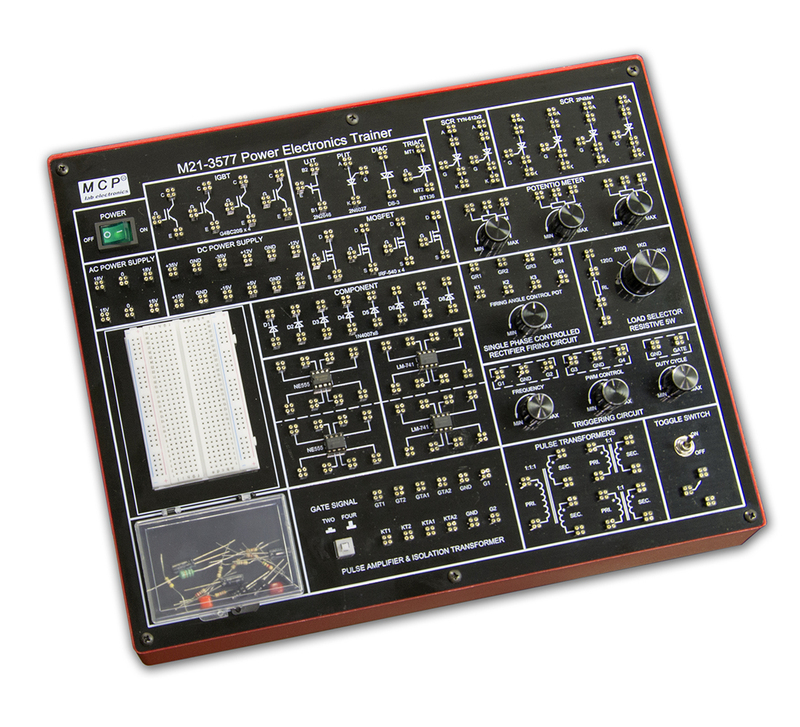
M21-3577 POWER ELECTRONICS TRAINER
Feature
.Comprehensive power Electronics trainer
.Know about the characteristics of the power electronics devices
.Learn the applications of the power devices
.Perform all essential power electronics circuit experiments
.Useful for students at engineering / technical institutes and R&D person in research labs
. Integration control panel, to make operation easy and safe
.4-point terminal, to make connection reliable
.On board element box of component set, to make use easy
Specification
1. Bread Board
Consisting of two Terminal Strips with 300 tie points and two Distribution Strips with 50 tie points each,
totaling to 400 tie points
2. DC Power Supply
± 5V/200mA, ± 12V/200mA, ± 15V/200mA, ± 35V/ 100mA
3. AC Power Supply
18V - 0V - 18V /200mA, 15V - 0V - 15V /200mA
4. Triggering Circuit
5 gates signal output, Frequency range : 40Hz to 900Hz Variable,
Amplitude : 12V PWM control of G1, G2, G3 and G4, Duty cycle control of "Gate" signal is 0 to 100%
5. Single Phase Rectifier
Firing angle control 0°-180° variables
6. Pulse Amplifier and Firing Circuit
Four gates signal output with isolation
7. SCR Assembly
2P4M x 4, (600V, 2A)
8. Power Devices
IGBT-G4BC20S x 4, MOSFET-IRF540 x 4, UJT-2N2646, DIAC-DB3, TRIAC-BT136, PUT-2N6027, SCR-TYN- 612 x 2
9. Circuit Component
Diode-1N4007 x 8, NE555 x 2, LM-741 x 2
10. Potentiometer
4.7kΩx 2, 1MΩ
11. Load Resistance
(5W) 120Ω, 270Ω, 1kΩ, 2.2kΩ
12. Pulse Transformer
1:1 x 2 , 1:1:1
13. Toggle Switch
SPDT
14. Component Set in Element Box
Resistor: (1/4W) 47Ωx2, 100Ωx2, 220Ωx2, 510Ωx4, 820Ωx2, 1kΩx2,
2.7kΩx4, 5.1kΩx2, 10kΩx3, 22kΩ, 33kΩ, 47kΩ,(5W)22Ω,(2W)100Ω,220Ω
Capacitor: 0.01uF, 0.047uF, 0.1uF, 0.33uF, 1uF/63Vx4, 2.2uF/50V
Inductor: 10mH, 68mHx2
Zener 9V
15. Patch Cord
20cm Red & Black 10 each, 40cm Red & Black 5 each
16. Input Voltage: 110~127VAC±10% 60Hz,220-240±10% 50Hz, Switchable
17. Dimensions (W×H×D): 334×95×258mm
18. Weight: 4.5kg
EXPERIMENTS CONTENT
01. To study the characteristics of SCR and plot its V-I Characteristics.
02. To study the Gate control characteristics of SCR and it’s graph
03. To study the characteristics of UGT and calculate interbase resistance and intrinsic standoff ratio
04. To study the characteristics of MOSFET
05. To study the characteristics of IGBT
06. To study the characteristics of DIAC and plot its V-I characteristics curve
07. To study the V-I characteristics of TRIAC
08. To study the characteristics of PUT
09. To study of class B commutation circuit
10. To study of class C commutation circuit
11. To study of class D commutation circuit
12. To study of class F commutation circuit
13. To study the Resistor Triggering circuit
14. To study the Resistor-Capacitor Triggering Circuit (Half wave)
15. To study the Resistor-Capacitor Triggering Circuit (Full wave).
16. To study the triggering of SCR using UJT
17. To study the Triggering of SCR using 555 IC.
18. To study the Triggering of SCR using Op-Amp 741 IC
19. To study of the ramp and pedestal triggering using anti-parallel SCR in AC load
20. To study of the UJT relaxation oscillator
21. To study of the voltage commutated chopper
22. To study of the Bedford inverter
23. To study of the single phase PWM inverter using MOSFET
24. To study of the single phase PWM inverter using IGBT
25. To study the half-wave-controlled rectifier with resistive load
26. To study the half wave-controlled rectifier with RL load
27. To study the full-wave controlled rectifier (mid-point configuration) with resistive load
28. To study the full-wave controlled rectifier (mid point configuration) with RL load
29. To study the fully controlled bridge rectifier with resistive load
30. To study the fully controlled bridge rectifier with RL load